The ForceTronics blog provides tutorials on creating fun and unique electronic projects. The goal of each project will be to create a foundation or jumping off point for amateur, hobbyist, and professional engineers to build on and innovate. Please use the comments section for questions and go to forcetronics.com for information on forcetronics consulting services.
In this video we design a low cost driver circuit for a four wire bipolar stepper motor using two H bridges.
//********************Arduino code from video*********************** #include <Stepper.h> const int numberOfSteps = 100; //number of steps you want your stepper motor to take // initialize the stepper library on pins 8 through 11: Stepper myStepper(numberOfSteps, 8, 9, 10, 11); void setup() { // set the speed at 60 rpm: myStepper.setSpeed(60); } void loop() { myStepper.step(numberOfSteps); delay(1000); }
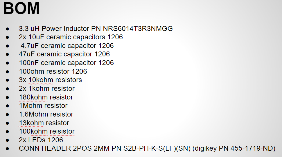
In this video series we build the ultimate battery circuit that can handle various battery chemistry's, charge batteries, perform load sharing during charging, handle input voltage levels that are higher or lower than the output, and more. In part 2 we will look at the PCB layout with a focus on the buck boost DC to DC Converter and look at the BOM.
In this video series we build the ultimate battery circuit that can handle various battery chemistry's, charge batteries, perform load sharing during charging, handle input voltage levels that are higher or lower than the output, and more. In part 1 we will look at the circuit configuration and component values that we plan to use.
In this video we look at how to make a simple DC electronic load with Arduino and some simple components. In part two 2 we add some flexible measurement capabilities.
//***************************Arduino Code************************************************* #include <Average.h>
/*
* This code was used for a tutorial on how to build a simple eload with Arduino
* The Tutorial can be found on the ForceTronics YouTube Channel
* This code is public domain and free for anybody to use at their own risk
*/
//Uncomment AVGMEAS to print out avg measurement data and uncomment FASTMEAS to print fast voltage or current measur
#define AVGMEAS
//#define FASTMEAS
//uncomment to print fast current measurements, leave commented to print fast voltage measurements
//#define FASTAMP
//The following variables set the eload sequence
const int sValues[] = {20,50,280}; //set the DAC value for each step
const unsigned long sTime[] = {350,50,15}; //set the dwell time for each step
const int sNum = 3; //number of steps in the sequence, this number should match the number or items in the arrays
long repeat = -1; //set the number of times the sequence repeats, -1 means infinite
//The following variables control the measurement rates
int measInterval = 5; //in milli seconds, fast measurement rate. This should be less than or equal to measAvgInt
int measAvgInt = 1000; //this is done in milliseconds and should be a multiple of the meas interval
int aCount = 0; //tracks where we are in the sequence
unsigned long sStart; //trcks when a sequence step starts its timer
unsigned long mStart; //tracks when a new measurement interval starts
unsigned long aHours = 0; //holds amp hour value
const unsigned long m2Hours = 360000; //constant value for converting mil sec to hours
const float lRes = 5.08; //exact value of eload resistor --> 5.08
const float rMult = 1.51; //multiplier for resistor divider network: R1 = 5.08k and R2 = 9.98k ratio is 9.98 / (9.98 + 5.08) = .663 --> 1.51
const byte aDCVolt = A2; //ADC channel for measuring input voltage
const byte aDCCurrent = A4; //ADC channel for measuring voltage across resistor
Average<float> voltMeas((measAvgInt/measInterval)); //create average obect to handle voltage measurement data
Average<float> currMeas((measAvgInt/measInterval)); //create average object to handle current measurement data
void setup() {
pinMode(A0, OUTPUT); //A0 DAC pin to output
analogWriteResolution(10); //default DAC resolution is 8 bit, swith it to 10 bit (max)
analogReadResolution(12); //default ADC resolution is 10 bit, change to 12 bit
Serial.begin(57600);
analogWrite(A0, sValues[aCount]); //Set DAC value for first step
sStart = mStart = millis(); //start timer for seq and measure interval
}
void loop() {
while(repeat > 0 || repeat < 0) { //loop controls how often sequence repeats
//timer for changing sequence step
if(timer(sTime[aCount],sStart)) {
aCount++; //go to next sequence step
if(aCount >= sNum) aCount = 0; //if at end go back to beginning
analogWrite(A0, sValues[aCount]); //Set DAC value for step
sStart = millis(); //reset timer
}
if(timer(measInterval,mStart)) {
voltMeas.push(inputVolt(aDC2Volt(analogRead(aDCVolt)))); //push value into average array
currMeas.push(inputCurrent(aDC2Volt(analogRead(aDCCurrent)))); //push value into average array
//print input voltage value and current values
#ifdef FASTMEAS
#ifdef FASTAMP
Serial.println(currMeas.get((currMeas.getCount() - 1))*1000); //serial print out of fast current measurements
#else
Serial.println(voltMeas.get((voltMeas.getCount() - 1))); //serial print out of fast voltage measurements
#endif
#endif
mStart = millis(); //reset timer
}
//print out average, max / min, and amp hour measurements
if(voltMeas.getCount() == (measAvgInt/measInterval)) {
#ifdef AVGMEAS
Serial.print("Average voltage: "); Serial.print(voltMeas.mean()); Serial.println(" V"); //get and print average voltage value
float mA = currMeas.mean()*1000; //get average current value in mA
Serial.print("Average current: "); Serial.print(mA); Serial.println(" mA"); //print current value
Serial.print("Max voltage: "); Serial.print(voltMeas.maximum()); Serial.println(" V"); //print max and min voltage
Serial.print("Min voltage: "); Serial.print(voltMeas.minimum()); Serial.println(" V");
Serial.print("Max current: "); Serial.print(currMeas.maximum()*1000); Serial.println(" mA"); //print max and min current
Serial.print("Min current: "); Serial.print(currMeas.minimum()*1000); Serial.println(" mA");
float aH = ampHoursCal(measAvgInt,mA); //calculate how much amp hours of current was consumed since start
if(aH < 1000) { Serial.print("Amp hours of power source: "); Serial.print(aH); Serial.println(" uAh"); } //print current in uA
else { Serial.print("Amp hours of power source: "); Serial.print(aH/1000); Serial.println(" mAh"); } //print current in mA
#endif
voltMeas.clear(); //clear voltage measurement array
currMeas.clear(); //clear current measurement array
}
if(repeat > 0) repeat--; //increment repeat if not infinite loop
}
}
//timer function that runs in mill second steps.
//Inputs are timer interval and timer start time
bool timer(unsigned long tInterval, unsigned long tStart) {
unsigned long now = millis(); //get timer value
if ((now - tStart) > tInterval ) return true; //check if interval is up
return false; //interval is not up
}
//converts raw ADC reading to voltage value based on 3.3V reference
//input is 12 bit ADC value
float aDC2Volt(int aDC) {
return (((float)aDC/4095)*3.3);
}
//function converts voltage value to input voltage value based off resistor voltage divider constant
//input is measured voltage
float inputVolt(float aVolt) {
return (rMult*aVolt);
}
//converts voltage measurement at load resistor to current measurement based on load resistor value
//Input is measured voltage
float inputCurrent(float rVolt) {
return (rVolt/lRes);
}
//This functions calculates amp hours
//amp hour = amp hour value + (amps * (mil sec / 360k)
//input: measInt is measurement interval in milli sec and aVal is the measured current value in mA
float ampHoursCal(int measInt, float aVal) {
aHours = aHours + (aVal * ((double)measInt/m2Hours)*1000); //this converts currect measurement to mA
return aHours;
}
In this video we look at how to make a simple DC electronic load with Arduino and some simple components.
//****************Arduino code from video************ /* * This code was used for a tutorial on how to build a simple eload with Arduino * The Tutorial can be found on the ForceTronics YouTube Channel * This code is public domain and free for anybody to use at their own risk */ void setup() { pinMode(A0, OUTPUT); //A0 DAC pin to output analogWriteResolution(10); //default DAC resolution is 8 bit, swith it to 10 bit (max) } void loop() { //create pulsed current profile analogWrite(A0, 16); //Set DAC to approximately 10mV --> current 10mV / 5ohm = 2 mA delay(500); analogWrite(A0,310); //Set DAC to 1V --> current 1V / 5ohm = 200 mA delay(50);
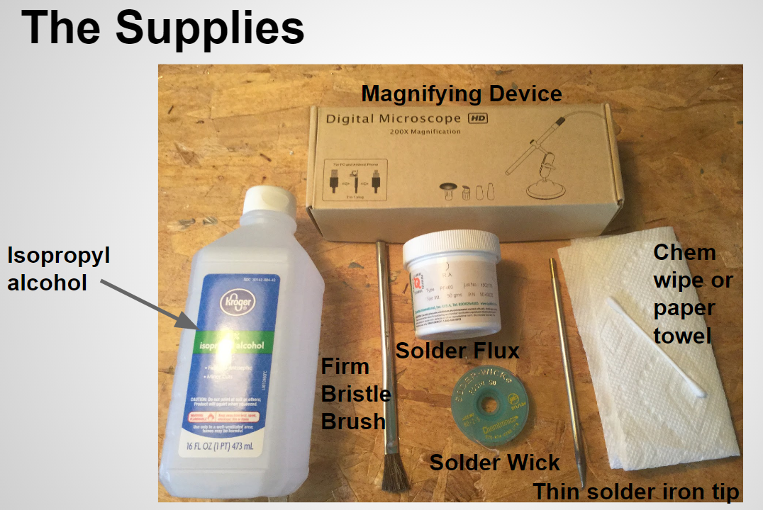
When you are prototyping, repairing, or hacking PCB boards you will most definitely find yourself in situations where you need to solder surface mount components / devices (SMD) by hand. In this video we look at two easy methods to solder SMD by hand with a basic solder station.
In this tutorial we look at how easy it is to integrate the popular Neo-7m GNSS / GPS module into your design without having to be an RF / microwave expert. In part 2 we build up our board and take it for a test drive.
In this tutorial we look at how easy it is to integrate the popular Neo-7m GNSS / GPS module into your design without having to be an RF / microwave expert.
In this video we look at how to use Arduino with the ThingSpeak IoT, cloud, and analytics platform. In the video we look at two use cases of ThingSpeak. For the first use case we log wireless sensor data to the cloud and perform post processing on the data using MATLAB. In the second use case we monitor a room with a wireless motion detector setup and have ThingSpeak send out a Tweet if any movement is detected in the room.
//*****************Arduino code from video********************************** /* This sketch was created for a video tutorial on the ForceTronics YouTube that shows how to use Arduino with the ThingSpeak cloud This code is public domain and free for anybody to use or modify at their own risk Note this code was leveraged from: Arduino --> ThingSpeak Channel via MKR1000 Wi-Fi Created: May 7, 2016 by Hans Scharler (http://www.nothans.com) */ #include <SPI.h> #include <WiFi101.h> //This sketch should work with any Arduino or shield that can use the WiFi101 library
char ssid[] = "YourNetwork"; // your network SSID (name) char pass[] = "YourPassword"; // your network password int status = WL_IDLE_STATUS; // Initialize the Wifi clients WiFiClient tClient; //this one is used to post temperature data WiFiClient mClient; //this one is used to post motion detection data // ThingSpeak Settings char server[] = "api.thingspeak.com"; String writeAPIKey = "YourWriteKey"; //Timing variables for tracking temperature posting unsigned long tempLastConnectionTime = 0; // track the last connection time const unsigned long tempPostingInterval = 295000L; // post temp ADC value just under every 5 min //Timing and logic variables for tracking temperature posting unsigned long mLastConnectionTime = 0; // track the last connection time const unsigned long mPostingInterval = 30000L; //checks to see if motion was detected every 30 sec bool mReset = true; //tracks if motion detection has been reset void setup() { pinMode(2,INPUT); //digital pin used to read output of motion detector pinMode(6,OUTPUT); //LED pin used to know when data is sent to cloud // attempt to connect to Wifi network while ( status != WL_CONNECTED) { // Connect to WPA/WPA2 Wi-Fi network status = WiFi.begin(ssid, pass); // wait 10 seconds for connection delay(10000); } } void loop() { //timer to know when it is time to post temp data to cloud if (millis() - tempLastConnectionTime > tempPostingInterval) { digitalWrite(6,HIGH); //Use the LED to see if Arduino gets heldup posting data to the cloud tempHttpRequest(); //function that formats data strings and posts data to ThingSpeak cloud digitalWrite(6,LOW); } if (millis() - mLastConnectionTime > mPostingInterval) { digitalWrite(6,HIGH); //Use the LED to see if Arduino gets heldup posting data to the cloud if(digitalRead(2) && mReset) { //if motion was detected post it mReset = false; //motion detected so reset variable mHttpRequest(); //if true motion was detected so post to cloud } else mReset = true; //reset logic tracker digitalWrite(6,LOW); } } //Posts temp data to thingspeak cloud void tempHttpRequest() { // read analog pin 0 with temp sensor connected int sensorValue = analogRead(0);
// create data string to send to ThingSpeak String data = String("field1=" + String(sensorValue, DEC));
// POST data to ThingSpeak if (tClient.connect(server, 80)) { tClient.println("POST /update HTTP/1.1"); tClient.println("Host: api.thingspeak.com"); tClient.println("Connection: close"); tClient.println("User-Agent: ArduinoWiFi/1.1"); tClient.println("X-THINGSPEAKAPIKEY: "+writeAPIKey); tClient.println("Content-Type: application/x-www-form-urlencoded"); tClient.print("Content-Length: "); tClient.print(data.length()); tClient.print("\n\n"); tClient.print(data); // close any connection before sending a new request tClient.stop(); // note the last connection time tempLastConnectionTime = millis(); } } //posts motion detection data to thingspeak cloud void mHttpRequest() {
// create data string to send to ThingSpeak, we always send a one here to indicate motion detected String data = String("field2=" + String(1,DEC));
// POST data to ThingSpeak if (mClient.connect(server, 80)) { mClient.println("POST /update HTTP/1.1"); mClient.println("Host: api.thingspeak.com"); mClient.println("Connection: close"); mClient.println("User-Agent: ArduinoWiFi/1.1"); mClient.println("X-THINGSPEAKAPIKEY: "+writeAPIKey); mClient.println("Content-Type: application/x-www-form-urlencoded"); mClient.print("Content-Length: "); mClient.print(data.length()); mClient.print("\n\n"); mClient.print(data); // close any connection before sending a new request mClient.stop(); // note the last connection time mLastConnectionTime = millis(); } }
%*************************MATLAB code from video***************************
In this video we look at what are compiler directives and how they can come in handy.
//***********************Arduino code from the video*********** /* * This code was made for a video tutorial on ForceTronics YouTube Channel called "Using Compiler Directives with Arduino" * This code free to be used or modified by anybody at your own risk * */ //#define SERIAL_PRINT 1 #define ADC_PIN (uint8_t)A0 #ifdef SERIAL_PRINT #define _SERIAL_BEGIN(x) Serial.begin(x); #define _SERIAL_PRINT(x) Serial.print(x); #define _SERIAL_PRINTLN(x) Serial.println(x); #else #define _SERIAL_BEGIN(x) #define _SERIAL_PRINT(x) #define _SERIAL_PRINTLN(x) #endif void setup() { _SERIAL_BEGIN(57600); //start serial comm if enabled //This will only print if SERIAL_PRINT is 1 _SERIAL_PRINTLN("We are going to take an ADC reading every 2 sec..."); } void loop() { _SERIAL_PRINT("The latest ADC measurement is "); _SERIAL_PRINTLN(analogRead(ADC_PIN)); delay(2000); }
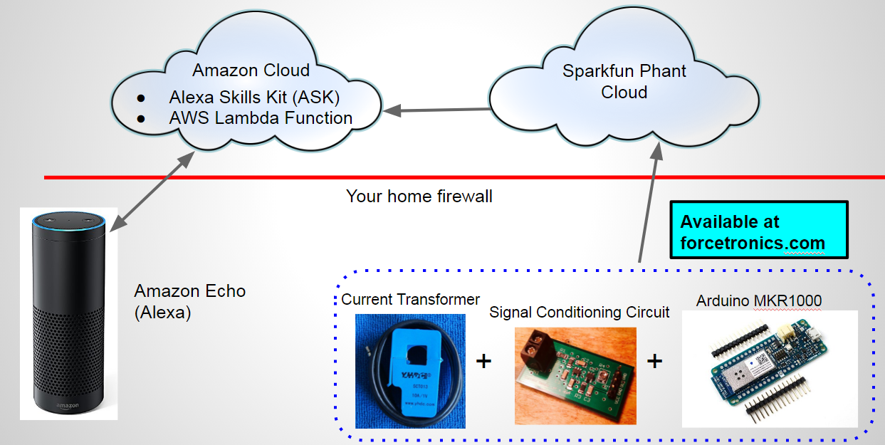
In the final conclusion of this four part series on using the Amazon Echo and Arduino for home automation we look at the Arduino hardware setup for monitoring the current consumption of a washer machine and reports its state to the cloud.
In part 3 instead of controlling a household device with the Echo, Arduino, and the cloud like we did in parts 1 and 2, we are monitoring an appliance (washer) so the data is flowing in the opposite direction.
In this video we look at how we can use Bare Conductive's Electric Paint to create a custom strain gauge.
/* * This code was written for a video on the ForceTronics YouTube channel. This code is public domain and can be used and modified by anybody at your own risk */ #include <Average.h> //Call average library void setup() { Serial.begin(57600); analogReadResolution(12); //Set Arduino Zero ADC to 12 bits for(int i=0;i<4;i++) analogRead(A0); //burn a couple readings since we changed ADC setting Average<int> ave(10); } void loop() { delay(100); Average<int> ave(10); //Create average object for (int i=0; i<10;i++) ave.push(analogRead(A0) - 2700); //get 10 readings and subtract most of the value off to look at small changes Serial.println(ave.mean()); //average the 10 readings together }
In this video series we look at how to use Arduino (ESP8266) and the Amazon Echo to do voice controlled home automation.
Link to project material on GitHub:https://github.com/ForceTronics/Arduino_Echo_Home_Automation //************************************ESP8266 Arduino code********************* /* This sketch was created for a video series called Home Automation with the Arduino and the Amazon Echo Part 2 That was presented on the ForceTronics YouTube Channel. This code is public domain for anybody to use or modify at your own risk Note that this code was leveraged from a Sparkfun example on using their cloud service Phant */ // Include the ESP8266 WiFi library #include <ESP8266WiFi.h> // Include the SparkFun Phant library. #include <Phant.h> //Set your network name and password const char WiFiSSID[] = "NetworkName"; //your wifi network name goes here const char WiFiPSK[] = "NetworkPassword"; //your wifi password goes here //define constants for pin control and node number const int light = 4; //NodeMCU GPIO 4 pin is connected to the WiFi AC Switch control const char parseKey[] = "stamp"; //This is used to parse through data from Phant to find light setting //declare phant address and security keys const char PhantHost[] = "data.sparkfun.com"; const char gPublicKey[] = "YourPublicKey"; //your phant public key goes here const char gPrivateKey[] = "YourPrivateKey"; //your phant private key goes here //specify the rate that you post data to cloud const unsigned long postRate = 1000; unsigned long lastPost = 0; void setup() { initHardware(); //setup arduino hardware connectWiFi(); //Connect your WiFi network digitalWrite(LED_BUILTIN, HIGH); //turn on LED } void loop() { //loop until it is time to post data to phant cloud, variable "postRate" defines the interval in milli seconds if (lastPost + postRate <= millis()) { if (getFromPhant()) lastPost = millis(); //get data from Phant else lastPost = millis(); //Even if we fail delay whole cycle before we try again } } //function used to connect to WiFi network void connectWiFi() { byte ledStatus = LOW; // Set WiFi mode to station (as opposed to AP or AP_STA) WiFi.mode(WIFI_STA); // WiFI.begin([ssid], [passkey]) initiates a WiFI connection // to the stated [ssid], using the [passkey] as a WPA, WPA2, // or WEP passphrase. WiFi.begin(WiFiSSID, WiFiPSK); // Use the WiFi.status() function to check if the ESP8266 // is connected to a WiFi network. while (WiFi.status() != WL_CONNECTED) { // Blink the LED digitalWrite(LED_BUILTIN, ledStatus); // Write LED high/low ledStatus = (ledStatus == HIGH) ? LOW : HIGH; // Delays allow the ESP8266 to perform critical tasks // defined outside of the sketch. These tasks include // setting up, and maintaining, a WiFi connection. delay(100); } } //function that sets up some initial hardware states void initHardware() { pinMode(light, OUTPUT); //turn light off at startup digitalWrite(light, LOW); } //function that handles getting data from phant cloud int getFromPhant() { //Set phant data Phant phant(PhantHost, gPublicKey, gPrivateKey); WiFiClient client; //Create client object to communicate with the phant server
if (!client.connect(PhantHost, 80)) { //Attempt to connect to phant server using port 80 // If we fail to connect, return 0. return 0; } //Get data from phant cloud client.print(phant.get()); client.println(); int cTrack = 0; //variable that tracks count to spell stamp bool match = false; //tracks when we have a match with "stamp" and we can then get control data int pCount = 0; //variable used to track when we have control data while(1) { //loop until we get data and server closes connection if (client.available()) { //if data is available from phant server char c = client.read(); //read a bite of data from server if(!match) { //if true than we have not found the word "stamp" so keep looking if(c == parseKey[cTrack]) //check if we have a character match with word "stamp" { if(cTrack == (sizeof(parseKey)-2)) match = true; //if true it means we found a match for "stamp" in data from phant cloud cTrack++; //iterate this count if a character match was found } else { //if true means no character match so reset count cTrack = 0; } } else { //if true it means we found a match to "stamp" and we are ready to get control data if(pCount == 1) { //if true we are at the point in the data to read control data for node oen int dControl = c - '0'; //convert char data to an int by subtract an ASCII zero if(dControl == 1 | dControl == 0) digitalWrite(light, dControl); //make sure data is a one or zer and set LED pin with it } pCount++; //iterate the parse counter } } // if the server's disconnected, stop the client: if (!client.connected()) { client.stop(); //stop client, if you don't have this you will create too many clients and server won't let you connect anymore break; //This is how we get out of the loop } } return 1; // Return success }
//********************java script code for Lambda Function*************************
var https = require('https') //include https
exports.handler = (event, context) => {
try {
if (event.session.new) {
// New Session
console.log("NEW SESSION") //log this for debugging
}
switch (event.request.type) {
case "LaunchRequest":
// Launch Request
console.log(`LAUNCH REQUEST`)
context.succeed(
generateResponse(
buildSpeechletResponse("Welcome to the ForceTronics Home Automation Skill, say turn light on or turn light off", true), //response for Alexa if you just call the skill without intent
{}
)
)
break;
case "IntentRequest":
// Intent Request
console.log(`INTENT REQUEST`)
switch(event.request.intent.name) { //switch statement to select the right intent
case "TurnLightOn":
var endpoint = "https://data.sparkfun.com/input/YourPublicKey?private_key=YourPrivateKey&lightstate=1" //https string to log data to phant phant
https.get(endpoint, function (result) { //use https get request to send data to phant
console.log('Success, with: ' + result.statusCode);
context.succeed(
generateResponse( //if you succeeded allow Alexa to tell you state of light
buildSpeechletResponse("The light is turned on", true),
{}
)
)
}).on('error', function (err) {
console.log('Error, with: ' + err.message);
context.done("Failed");
});
break;
case "TurnLightOff": //the turn light off intent
var endpoint2 = "https://data.sparkfun.com/input/YourPublicKey?private_key=YourPrivateKey&lightstate=0" // phant string to set light state to off
https.get(endpoint2, function (result) {
console.log('Success, with: ' + result.statusCode);
context.succeed(
generateResponse( //Alexa response if successful
buildSpeechletResponse("The light is turned off", true),
{}
)
)
}).on('error', function (err) {
console.log('Error, with: ' + err.message);
context.done("Failed");
});
break;
default:
throw "Invalid intent"
}
break;
case "SessionEndedRequest":
// Session Ended Request
console.log(`SESSION ENDED REQUEST`)
break;
In this video we look at how to remove solder bridges from small surface mount components. When dealing with really small pins the task of removing solder bridges can seem intimidating, but as you will see in this video it is not tough at all if you have the right tools and know how for the job.
In this three part series we look at how to design a signal conditioning circuit to increase the accuracy and resolution of your ADC sensor measurements. The signal conditioning circuit consists of a double pole active Sallen Key Low Pass Filter and a non-inverting op amp. The filter portion is meant to attenuate high frequency noise from your sensor signal to increase measurement accuracy. The amplifier portion scales the signal up to the full range of the ADC to ensure you are getting max resolution. In part 3 we test our finished LPF + Amp circuit.
In this three part series we look at how to design a signal conditioning circuit to increase the accuracy and resolution of your ADC measurements. The signal conditioning circuit consists of a double pole active Sallen Key Low Pass Filter and a non-inverting op amp. The filter portion is meant to attenuate high frequency noise from your sensor signal to increase measurement accuracy. The amplifier portion scales the signal up to the full range of the ADC to ensure you are getting max resolution. In part 2 we do the PCB layout of our circuit using Eagle CAD software.
You can access the Eagle files on Github at: https://github.com/ForceTronics/Sallen-Key-Low-Pass-Filter-Design/tree/master
In this three part series we look at how to design a signal conditioning circuit to increase the accuracy and resolution of your ADC measurements. The signal conditioning circuit consists of a double pole active Sallen Key Low Pass Filter and a non-inverting op amp. The filter portion is meant to attenuate high frequency noise from your sensor signal to increase measurement accuracy. The amplifier portion scales the signal up to the full range of the ADC to ensure you are getting max resolution.
In this video we look at how you can access six additional digital pins from your Arduino Zero board. We also take a look at some flexible wired communication options you can take advantage of on the Arduino Zero.
Link to Adafruit tutorial referenced in the video: https://learn.adafruit.com/using-atsamd21-sercom-to-add-more-spi-i2c-serial-ports/creating-a-new-serial
Path on Windows to get to variants.cpp: C:\Users\yourname\AppData\Local\Arduino15\packages\arduino\hardware\samd\1.6.6
Zero pin out chart from video:
//**********************Arduino Code from the video*********************
//This code is free to use and modify at your own risk
bool tog = false; //used to toggle LEDs on and off
void setup() {
pinMode(38,OUTPUT); //This is the pin labeled "ATN"
pinMode(22,OUTPUT); //This is MISO pin on ICSP header
pinMode(20,OUTPUT); //This is SDA pin
SerialUSB.begin(57600); //this is the native USB port
Serial.begin(57600); //this is the programming port
Serial1.begin(57600); //this is for pins D0 and D1
}
void loop() {
if(tog) { //set each of the pins to high to turn LEDs on
digitalWrite(38,HIGH);
digitalWrite(22,HIGH);
digitalWrite(20,HIGH);
tog = false;
}
else { //set each pin to low to turn them off
digitalWrite(38,LOW);
digitalWrite(22,LOW);
digitalWrite(20,LOW);
tog = true;
}